This tutorial comes courtesy of Fighting 1:18th member, Ian Walker. His forum handle is XOC2008.
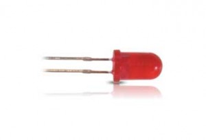
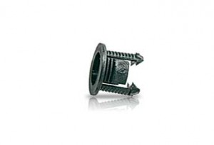
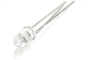
This tutorial is to show a basic means of wiring LEDs for your project. Key points here at the start are to identify where you plan to hide the batteries, locating a spot for the switch(es) you intend to use, drilling any necessary spots for the LEDs, and making sure everything will fit back together when completed. If using 5mm LEDs, I suggest getting a pack of LED holders. The LEDs will clip into the holder, and you drill the holes to a size where the holders(+ LEDs) will simply snap into place. (Note: Most LEDs will have their size identified on the pack they come in. The most common for these projects are 3mm and 5mm. I’m using 5mm for this example.)
 |
 |
 |
For this example we will assume we are wiring up a helicopter with two blinkers and a spotlight.
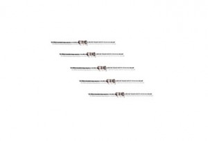
One mistake some people make at times(including myself), is not using resistors on blinking LEDs. On a single battery(or compartment) this helps prevent the draw of power which dims the solid state LED each time the blinker flashes on. Since we are only using anywhere from 3 to 9 volts maximum, your resistor does not need to have a high resistance.
I will also add for those unfamiliar with it, if you want good solid soldered connections, do not let the solder heat up on the tip of the gun. You heat the area you want the solder to go, and then touch the end of the solder to that area(while still applying heat with the gun) so it can flow where you need it. Heating solder on the tip of the gun burns it if it sits too long, preventing power from flowing unimpeded, and it does not create strong and lasting connections.
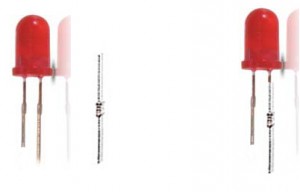
Identify the positive lead of the blinking LED and twist either end of the resistor to the lead, then solder in place. Repeat for the second blinker. (Note: The positive lead of any LED not attached to a circuitboard will be the longer of the two.)
You can of course clip the leads shorter, but remember not to clip the negative side till you’ve done your soldering to the positive lead or you will have to trial-wire it, and often if you get this wrong it can do damage to the LED preventing it from working. Once the resistor is in place, twist the end of a length of positive(red) wire to the other end of the resistor and solder in place. If you have heat-shrink tubing, now would be a good time to apply it, so you don’t have any shorts. If you do not have heat-shrink tubing, electrical tape will work, and you will want some handy for some of the more difficult connections.
In the example, we have a blinker at the tail and another just behind the main rotor, so you will have to cut your wires to an approximate length making sure you can get all the unsoldered ends to meet with some slack to work with. This includes the wires from the solid state spotlight.
Repeat these steps with the negative lead of the LED, minus the resistor. You can also wire and solder the leads of the solid state LED for the spotlight, though again, you will not need a resistor.
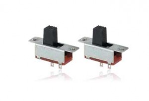
At this point, you will want to set both your switch(es) and where you plan on holding the batteries, so you will know just how much wire to use. Once those are set and you have located which pole on the switch is for the battery and which runs to the LEDs, I would suggest soldering the positive connection from the battery to the switch(es) so you don’t forget. Make certain your switch(es) is/are in the ‘off’ position while you continue.
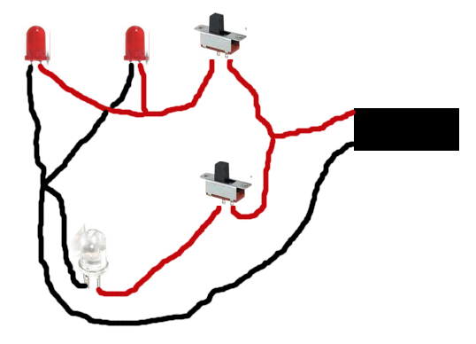
Take your positive wires and if by this point you have more than enough slack, you can trim a bit of excess before twisting the ends and soldering them all together, including a length running from the switch. Tape them up once they are secured, and tuck them away. Repeat with the negative(black) wires, and attach them to the negative from the battery compartment. The following is essentially what it should look like when you’ve gotten all your connections soldered:
Test the LEDs and switches again while your project is open. If you wait till you have closed it up, this can lead to a lot of frustration. Once you are assured that all the connections work and are secure, that you can jostle the project a little and nothing shorts out, I suggest using small pieces of the electrical tape to secure the wires to one side so they don’t get pinched while closing up.
Now close up your project and enjoy the fruits of your labor!
If you would like to comment on this article, please join the discussion here: http://forums.fighting118th.com/showthread.php?t=4238
If you are not already a member, than please, register with us.
 The Fighting 1:18th! The best Military 1:18 scale site on the net!

![[Tutorial] Scrimming by TIE_FighterTk069 [Tutorial] Scrimming by TIE_FighterTk069](https://www.fighting118th.com/wp-content/uploads/2014/11/Scrimming-Tutorial-1-272x125.jpg)


Sweet. I will have to add some lights to my next project!
Thanks! Must try this!